|
<< Click to Display Table of Contents > Cylinder |
  
|
|
<< Click to Display Table of Contents > Cylinder |
|
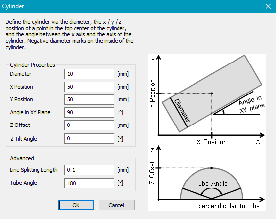
Figure 414: 3D Surfaces Cylinder dialog
Cylinder: Select Cylinder in the mode drop-down list and enable it. Click on ![]() to open the settings dialog.
to open the settings dialog.
Cylinder properties: Defines the diameter and position of the cylinder.
Diameter: Defines the diameter of the tube. Negative values are also allowed to mark inside a cylinder.
X, Y Position: Defines the X, Y position of the tube.
Angle in XY Plane: Defines the tube angle in the XY plane.
Z Offset: Defines the Z position of top of the tube. If the Diameter is negative this value defines the Z position of bottom of the tube.
Z Tilt Angle: Defines the Z slanting angle.
Advanced: Extended settings of tube marking.
Line Splitting Length: This parameter specifies the distance along a line after which a new point is generated and transformed on the 3D surface. Every individual line is split independently.
Tube Angle: Defines the maximal angle of the tube for the vector bending. This parameter affects the distance of the blue dashed lines in the View2D.
View2D: Four blue dashed lines indicates the location and size of the cylinder in the View2D. The View2D shows the vectors not bent around the tube.
Outer blue dashed lines: Defines the unwrapped size of the Tube Angle. Only vectors between these lines will be bend.
Inner blue dashed lines: Defines the wrapped size of the Tube Angle.
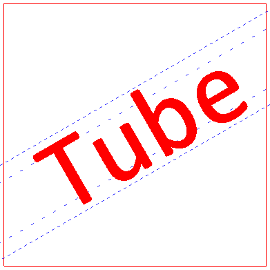
Figure 415: 3D Surfaces Cylinder View2D
3D preview: The bending of the vectors can be seen in the 3D view. Select at least one entity and click the 3D View button ![]() .
.
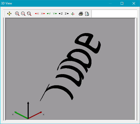
Figure 416: 3D Surfaces 3D preview.