|
<< Click to Display Table of Contents > Calibration |
  
|
|
<< Click to Display Table of Contents > Calibration |
|
A well calibrated system is the base for a precisely working marking system. This chapter describes the 2D and 3D calibration of scanner marking system.
Depending on the scan head, there are several options:
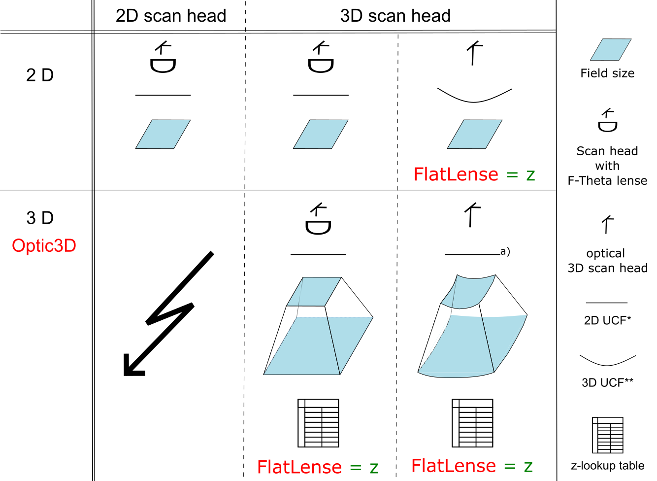
Figure 84: Calibration Options, Red = necessary licenses
•With a 2D scan head, only 2D applications are possible. For calibration, an F-Theta lense and a 2D UCF* (USC Calibration File) are needed.
•With a 3D scan head, the type of calibration depends on the required application and if there is an F-Theta lense integrated into the system:
oFor a 2D application with F-Theta lense, a 2D UCF* is needed.
oFor a 2D application without F-Theta lense, the FlatLense license (in order to access the z-axis for calibration) is required and a 3D UCF**.
•For 3D applications, the Optic3D license is required. Again, there are two types of calibration:
oWith an F-Theta lense, the FlatLense license, a 2D UCF* and additionally a z-lookup table is needed for calibration.
oWithout F-Theta lense, the FlatLense license, a 2D or 3D UCF* and a z-lookup table is needed for calibration.
* The 2D UCF can be acquired from the scan head manufacturer or created / edited with the correction file tool <SCAPS>\tools\sc_corr_table.
** The 3D UCF can be acquired from the scan head manufacturer. It is also possible to generate a 3D correction file with the correction file tool, but for this the 3D calibration with z-lookup table is necessary.
a) A 3D UDF can also be used, but SAMLight will ignore the z-values from the UCF file and use the z-values from the z-lookup table instead.